Turn on suggestions
Auto-suggest helps you quickly narrow down your search results by suggesting possible matches as you type.
Showing results for
Turn on suggestions
Auto-suggest helps you quickly narrow down your search results by suggesting possible matches as you type.
Showing results for
BIM Coordinator Program (INT) April 22, 2024
Find the next step in your career as a Graphisoft Certified BIM Coordinator!
Modeling
About Archicad's design tools, element connections, modeling concepts, etc.
- Graphisoft Community (INT)
- :
- Forum
- :
- Modeling
- :
- Re: How best to find the intersection points of tw...
Options
- Subscribe to RSS Feed
- Mark Topic as New
- Mark Topic as Read
- Pin this post for me
- Bookmark
- Subscribe to Topic
- Mute
- Printer Friendly Page
How best to find the intersection points of two GDL objects
Anonymous
Not applicable
Options
- Mark as New
- Bookmark
- Subscribe
- Mute
- Subscribe to RSS Feed
- Permalink
- Report Inappropriate Content
2010-04-25
08:50 AM
- last edited on
2023-05-23
04:50 PM
by
![]() Rubia Torres
Rubia Torres
If I want to split/trim the ends off each one, so they bi-sect neatly with each other, how can I get the cursor to snap to the exact intersection of the outside lines of each object? (Without tracing the object with temporary lines, from corner hotspot to corner hotspot)
This apparent inability (AFAIK) to get guidelines and cursor snaps with GDL objects is a serious disability. Is it an AC shortfall, or some switch that add-on/GDL programmers need to turn on when they create their objects?
I wonder, because it's kind of inconsistent - a CadImage's Profiler object has one side of its object's profile, in 2D, as a "hot line" (where the cursor changes to a mercedes and intersections can be found). Unfortuately, the line on the other side of the profile (for a rectangular profile, for example) is completely dead, so it's not a useable alternative for me.
I'd use Objective for a significant amount of modeling if the guidelines and snapping were available. As it is now, I only use it when I
10 REPLIES 10
Options
- Mark as New
- Bookmark
- Subscribe
- Mute
- Subscribe to RSS Feed
- Permalink
- Report Inappropriate Content
2010-04-25 11:22 AM
peter_h wrote:It is possible to create snappable edges on a GDL object. The trick is deciding where to put them. It's quite simple for the simplest shapes, e.g. rectilinear blocks, but the number of edges in a 3D body becomes enormous when curves are introduced, and particularly if the shapes is cut/rotated/bent.
Is it an AC shortfall, or some switch that add-on/GDL programmers need to turn on when they create their objects?
If every edge is snappable, the object could easily become a nuisance. We're working on an algorithm to calculate useful edge snaps, but this is a challenging problem when you are given so much freedom in 3D. Note that this problem doesn't occur in section/elevation views because the object appears as a group of (snappable) lines in those windows.
Ralph Wessel BArch
Anonymous
Not applicable
Options
- Mark as New
- Bookmark
- Subscribe
- Mute
- Subscribe to RSS Feed
- Permalink
- Report Inappropriate Content
2010-04-26 01:25 AM
Ralph wrote:Ralph: Just out of interest...do you mean that it could bog down the CPU, or be a problem with isolating the point you want to select when surrounded by too many snap-points? I assume you mean the latter, as the CPU has no problem with all lines being "hot" in section/elevation.
the object could easily become a nuisance
Thanks for pointing out that it's different - and works as I'd expect - in section/elevation. Not just Objective, but all GDL objects, as I've just discovered! I hadn't realised this before now
As for my 2cents with your future Objective improvements, relating to this issue...
How about a dropdown option in the Settings dialog:
a) No hot-lines
b) Hot-lines on long edges only {profile edges, not cuts}
c) Hot-lines on all edges {profile edges and cuts}
If this was user-selectable on a per-object basis, then we could customise the level of snapping, depending on the complexity of the object we are creating. So the decision as to what to make "hot" doesn't necessarily have to be automatic (and maybe not require as much coding of a sophisticated algorithm?).
This solution would suit me perfectly. If I had this option, I'd use Objective for ALL my framing and structural members, bar wall framing (which I'd like to be handled by the Cadimage addon, but I haven't gotten around to using it yet). So most of my uses of Objective would be timber rectilinear framing. So I'd mostly use option b, I'd imagine. Currently I'm barely using Objective for any of my framing
Options
- Mark as New
- Bookmark
- Subscribe
- Mute
- Subscribe to RSS Feed
- Permalink
- Report Inappropriate Content
2010-04-26 03:33 PM
peter_h wrote:Primarily the latter. A dense cloud of snap points can be a real pain to work around, especially when dimensioning. The former is also potentially an issue, but at the point where the object view is generated (refer to the next comment).
Just out of interest...do you mean that it could bog down the CPU, or be a problem with isolating the point you want to select when surrounded by too many snap-points?
peter_h wrote:Section views can take quite a while to generate (depending on size) because ArchiCAD has to generate a 3D body and then produce a hidden line view from it. If it did the same in plan, there could be a significant performance penalty. I believe this is why SEOs are not shown correctly in the plan view.
Why on earth is this super-productive ability crippled in plan-view - the most oft-used and useful view of all?
peter_h wrote:Thanks! Your feedback is much appreciated.
As for my 2cents with your future Objective improvements, relating to this issue...
Ralph Wessel BArch
Anonymous
Not applicable
Options
- Mark as New
- Bookmark
- Subscribe
- Mute
- Subscribe to RSS Feed
- Permalink
- Report Inappropriate Content
2010-04-26 03:49 PM
Section views can take quite a while to generate (depending on size) because ArchiCAD has to generate a 3D body and then produce a hidden line view from it. If it did the same in plan, there could be a significant performance penalty. I believe this is why SEOs are not shown correctly in the plan view.hmm...so im curious...how GS team can make SEO working in plan ? Do you Ralph have any idea cos you are familiar with these limitations of archicad and programing...i m wondering cos this is very needed option in archicad ?
Options
- Mark as New
- Bookmark
- Subscribe
- Mute
- Subscribe to RSS Feed
- Permalink
- Report Inappropriate Content
2010-04-26 04:10 PM
NeckoFromSarajevo wrote:I'm sure they've already done it for testing purposes and decided the performance penalty was too great. SEOs in ArchiCAD are not like the static boolean operations provided by many other 3D modellers. In those instances, the geometry created by the operation is persistent, so the overhead in displaying it in any view is quite light. ArchiCAD dynamically generates the geometry on demand, which can be very slow for some SEOs. We generally accept the delay in building a section/elevation or 3D view, but I'm not sure anyone would be pleased if the plan view took the same hit.
how GS team can make SEO working in plan ?
Ralph Wessel BArch
Anonymous
Not applicable
Options
- Mark as New
- Bookmark
- Subscribe
- Mute
- Subscribe to RSS Feed
- Permalink
- Report Inappropriate Content
2010-04-27 12:04 AM
I run into this situation regularly.
Usually, I'm working in architectural designs, and restrain my slopes and angles to those a framing contractor can measure in the field (i.e. with sloped beams meeting up with skewed rafters.
If you view a drawing in plan view, and elevation view perpendicular to each member in question, you should be able to zero in on the point in question in all (3) dimensions. That's the technology I leverage via ArchCAD.
In the AutoCAD days when I worked in other offices, I had to copy-paste the (4) elevation drawings into a plan worksheet and position them just so – so I could draw rays connecting specific points. I tore my hair out.
Now, I can toggle between differen 3D views.
Not sure if it helped for what you're doing. Let me know if you have questions.
B.S.
Anonymous
Not applicable
Options
- Mark as New
- Bookmark
- Subscribe
- Mute
- Subscribe to RSS Feed
- Permalink
- Report Inappropriate Content
2010-04-27 03:52 AM
bswain1 wrote:
"If you view a drawing in plan view, and elevation view perpendicular to each member in question, you should be able to zero in on the point in question in all (3) dimensions. That's the technology I leverage via ArchCAD."
Very interesting bswain1.
However, I'm not getting the concept in my head.
Any chance you could post simple example of what what your doing?
Thanks
lec
Options
- Mark as New
- Bookmark
- Subscribe
- Mute
- Subscribe to RSS Feed
- Permalink
- Report Inappropriate Content
2010-04-27 05:42 AM
I know what you mean and it would be nice if any object's lines represented in a plan view at least would automatically be snappable to edges and intersections, etc. without having to script them into the object.
But as Ralph said this could become messy and annoying.
They will automatically disappear when done (which can be good or bad depending if you need them again).
Very easy to place especially with the guide segment button.
Barry.
But as Ralph said this could become messy and annoying.
peter_h wrote:Have you tried using guide lines instead of actual lines.
(Without tracing the object with temporary lines, from corner hotspot to corner hotspot)
They will automatically disappear when done (which can be good or bad depending if you need them again).
Very easy to place especially with the guide segment button.
Barry.
One of the forum moderators.
Versions 6.5 to 27
Dell XPS- i7-6700 @ 3.4Ghz, 16GB ram, GeForce GTX 960 (2GB), Windows 10
Lenovo Thinkpad - i7-1270P 2.20 GHz, 32GB RAM, Nvidia T550, Windows 11
Versions 6.5 to 27
Dell XPS- i7-6700 @ 3.4Ghz, 16GB ram, GeForce GTX 960 (2GB), Windows 10
Lenovo Thinkpad - i7-1270P 2.20 GHz, 32GB RAM, Nvidia T550, Windows 11
Anonymous
Not applicable
Options
- Mark as New
- Bookmark
- Subscribe
- Mute
- Subscribe to RSS Feed
- Permalink
- Report Inappropriate Content
2010-04-27 03:40 PM
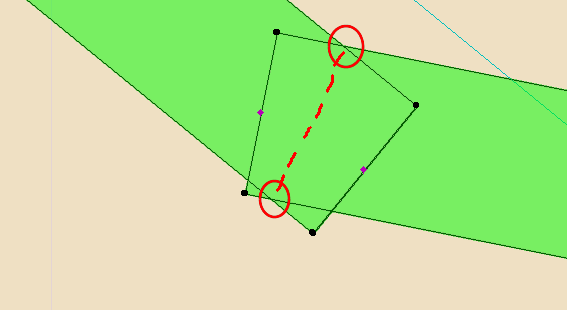
By toggling between two trace references of the two elevations, e.g. South and West, using a diagonal to locate points between the two, you can locate any point in x,y and z coordinates.
See attached image showing the West elevation trace references placed. They are placed so the reference elevations (e.g. ground level) intersect at the 45º diagonal as shown. The South elevation (turned off at the moment) is placed to the South.
You can see my guidelines representing the ground level and the point in question at the peak.
Usually, the 3D nature of BIM handles such issues without this procedure, except for little details like the one you're working with.
B.S.
Learn and get certified!

Still looking?
