Turn on suggestions
Auto-suggest helps you quickly narrow down your search results by suggesting possible matches as you type.
Showing results for
Turn on suggestions
Auto-suggest helps you quickly narrow down your search results by suggesting possible matches as you type.
Showing results for
BIM Coordinator Program (INT) April 22, 2024
Find the next step in your career as a Graphisoft Certified BIM Coordinator!
Modeling
About Archicad's design tools, element connections, modeling concepts, etc.
- Graphisoft Community (INT)
- :
- Forum
- :
- Modeling
- :
- Re: Questions about Wood siding and composite floo...
Options
- Subscribe to RSS Feed
- Mark Topic as New
- Mark Topic as Read
- Pin this post for me
- Bookmark
- Subscribe to Topic
- Mute
- Printer Friendly Page
Questions about Wood siding and composite floor - help
Anonymous
Not applicable
Options
- Mark as New
- Bookmark
- Subscribe
- Mute
- Subscribe to RSS Feed
- Permalink
- Report Inappropriate Content
2009-11-19 01:07 AM
In addition, In regards to the siding, I have used several short walls stacked. Each wall as you can see uses a custom profile. I would really like to see the tongue and groove in the documents, however the walls seems to be cleaning up. Is there another way to do this?
Thanks,

8 REPLIES 8
Anonymous
Not applicable
Options
- Mark as New
- Bookmark
- Subscribe
- Mute
- Subscribe to RSS Feed
- Permalink
- Report Inappropriate Content
2009-11-19 03:01 AM
^ I figured out the LINE on the concrete. I must have missed the setting earlier. But can someone please advice on the siding?
Options
- Mark as New
- Bookmark
- Subscribe
- Mute
- Subscribe to RSS Feed
- Permalink
- Report Inappropriate Content
2009-11-19 03:18 AM
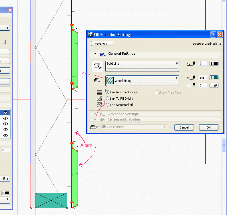
You could alter the Section Fill every-other Wall. Or make the siding Profile for the entire wall height rather than stacking individual Walls.
David Larrew, AIA, GDLA, GSRC
Architectural Technology Specialist
a r c h i S O L U T I O N S
WIN7-10/ OSX 10.15.7
AC 5.1-25 USA
Architectural Technology Specialist
a r c h i S O L U T I O N S
WIN7-10/ OSX 10.15.7
AC 5.1-25 USA
Anonymous
Not applicable
Options
- Mark as New
- Bookmark
- Subscribe
- Mute
- Subscribe to RSS Feed
- Permalink
- Report Inappropriate Content
2009-11-19 06:36 PM
You might consider using a complex for the whole wood siding wall... Either way though I find it simplest to leave a very small gap between (fills in complex profile) or walls if stacked vertically... I'd also make the tongue just a touch smaller than the grove.... What is happening is that AC is combining elements with the same material/fill.
Anonymous
Not applicable
Options
- Mark as New
- Bookmark
- Subscribe
- Mute
- Subscribe to RSS Feed
- Permalink
- Report Inappropriate Content
2009-11-19 06:39 PM
Hi
Maybe David has already answered your question, but thought I'd throw this in there just for fun.
Noticed you don't have different fills for each piece of V Rustic, and maybe you aren't looking for that, but here's how I did it.
Down side is, if you want each C.P. wall to show top "plate" fills and don't want to stretch V rustic, which would show up wider than other walls you did not stretch, you may need to make a few different flavors (heights) of this wall as I had to for my project. I'm addicted to my plates auto showing up in any cut I make if I can, (rake walls excluded for now).
HTMS.
lec
You could also do as Steve says and leave gap and then obviously would not need different fills.
But stretching problem remains.
Anonymous
Not applicable
Options
- Mark as New
- Bookmark
- Subscribe
- Mute
- Subscribe to RSS Feed
- Permalink
- Report Inappropriate Content
2009-11-21 04:05 AM
@Steve: what is a complex?
@lec: thank you for the screen shot. what do you mean about stretching the siding? also can you elaborate on your plates automatically showing. seems like your experience can really help me pull this section together the right way.
@lec: thank you for the screen shot. what do you mean about stretching the siding? also can you elaborate on your plates automatically showing. seems like your experience can really help me pull this section together the right way.
Anonymous
Not applicable
Options
- Mark as New
- Bookmark
- Subscribe
- Mute
- Subscribe to RSS Feed
- Permalink
- Report Inappropriate Content
2009-11-21 06:38 PM
I think what Steve is referring to is Complex Profile,
which is what we are all talking about, I believe.
Vertical stretching does not work well here with Horizontal siding as what starts out as, say 1x6 on a 8' wall, but vertically stretched to make a 9' wall, will cause the 1x6 to be more like maybe slightly less than 1x7, even worse on a taller wall. That's why you need different version of this type of wall.
A stretched wall will not match up in views of both, not that you couldn't do it, just looks wrong in 3d, elev and section.
Also, you might want to cut the first siding board flush (or better yet slightly angled) at the bottom for "drip-edge" and hang down a bit as a little more correctly shown in this "improved" version.
So even my Tyvek, (paper) under the siding has to be different than the either of the two fills I've used for siding and the shear ply fill (and it different than the stud fill) or they will join.
Lots of discussion on plates if you search, but here goes anyway.
The plates start out as one fill, then you use the split tool to slice it diagonally twice. Before you save, make sure to change the fills that touch to something different. It's ok if the points touch, just not the long sides. This is true for all the fills of C.P.s
In my example, only two different fills are needed for the plates, but the
one touching the stud can't be the same as the stud.
A bit confusing as first, but you'll get get if I
haven't muddied this up too much.
lec
Anonymous
Not applicable
Options
- Mark as New
- Bookmark
- Subscribe
- Mute
- Subscribe to RSS Feed
- Permalink
- Report Inappropriate Content
2009-11-22 05:59 AM
So are you plates a complex profile? Im a little loss. =( sorry.
BTW,
Is there a way to show object being obscured by another object as a hidden line?
I am working on this: I would to be able to see the beams and glass bellow the roof slab as hidden...


What is going to be the best way to represent a hollow core slab? The cantilever is not supposed to be a concrete slab but a HCS. I am thinking of using a complex profile for this... or is there a better way to maybe subtract the "hollowness" from a floor object? I am thinking somehow modeling a cylinder.
BTW,
Is there a way to show object being obscured by another object as a hidden line?
I am working on this: I would to be able to see the beams and glass bellow the roof slab as hidden...
What is going to be the best way to represent a hollow core slab? The cantilever is not supposed to be a concrete slab but a HCS. I am thinking of using a complex profile for this... or is there a better way to maybe subtract the "hollowness" from a floor object? I am thinking somehow modeling a cylinder.
Anonymous
Not applicable
Options
- Mark as New
- Bookmark
- Subscribe
- Mute
- Subscribe to RSS Feed
- Permalink
- Report Inappropriate Content
2009-11-24 06:45 PM
Profoxcg wrote:"So are your plates a complex profile?"
The wall and all it's components I'm showing are one Complex Profile.
"Is there a way to show object being obscured by another object as a hidden line?" Yes, but;...
I don't think you can show two objects lower as dashed, as; glass below beam below slab as I think you were asking, AFAIK. Others may know how to.
You may effectively get what you want with multiply saved views and their F.P.C.P. control.
Look at: Document>Floor Plan Cut plane (do a search) for showing dashed lines below F.P.C.P.
I think there is a post describing footings dashed below a stem walls solid lines, but the concept is the same.
lec
Learn and get certified!

Still looking?
