Turn on suggestions
Auto-suggest helps you quickly narrow down your search results by suggesting possible matches as you type.
Showing results for
Turn on suggestions
Auto-suggest helps you quickly narrow down your search results by suggesting possible matches as you type.
Showing results for
BIM Coordinator Program (INT) April 22, 2024
Find the next step in your career as a Graphisoft Certified BIM Coordinator!
Modeling
About Archicad's design tools, element connections, modeling concepts, etc.
- Graphisoft Community (INT)
- :
- Forum
- :
- Modeling
- :
- Door In Complex Wall Profile Incorrect
Options
- Subscribe to RSS Feed
- Mark Topic as New
- Mark Topic as Read
- Pin this post for me
- Bookmark
- Subscribe to Topic
- Mute
- Printer Friendly Page
Door In Complex Wall Profile Incorrect
Anonymous
Not applicable
Options
- Mark as New
- Bookmark
- Subscribe
- Mute
- Subscribe to RSS Feed
- Permalink
- Report Inappropriate Content
2006-07-25
05:36 PM
- last edited on
2023-05-26
11:38 AM
by
![]() Rubia Torres
Rubia Torres
17 REPLIES 17
Anonymous
Not applicable
Options
- Mark as New
- Bookmark
- Subscribe
- Mute
- Subscribe to RSS Feed
- Permalink
- Report Inappropriate Content
2006-07-25 05:37 PM
Anonymous
Not applicable
Options
- Mark as New
- Bookmark
- Subscribe
- Mute
- Subscribe to RSS Feed
- Permalink
- Report Inappropriate Content
2006-07-25 08:00 PM
Jay,
I just made a complex profile wall very similar to yours
and put a window and door into it and found that
they had all sorts of strange problems in 3D
including the ones you mentioned.
The door did not cut the brick wainscot, the exterior casing
separated from the jamb, and the jamb depth was some
arbitrary dimension that did not fit in the wall.
The window cut into the wainscot in 3D but not in 2D
but otherwise seemed ok.
Peter Devlin
Options
- Mark as New
- Bookmark
- Subscribe
- Mute
- Subscribe to RSS Feed
- Permalink
- Report Inappropriate Content
2006-07-26 12:38 AM
There's so many things to consider (and then the complex profile system is full of bugs anyway IMHO).
To correct the 3D view, have you checked the following?:
Opening Reference is checked in the Profile Editor and the lines are positioned correctly;
Your door's 'Opening Plane' is 'Associated to Wall' (parameters panel);
For your 2D view:
I think this is just a bug mate. At least I haven't found a way to make it appear properly yet. Maybe someone else has?....
Cheers,
Link.
Options
- Mark as New
- Bookmark
- Subscribe
- Mute
- Subscribe to RSS Feed
- Permalink
- Report Inappropriate Content
2006-07-26 04:37 PM
Jay wrote:Jay:
We have a complex wall profile that has a 4' wainscot and a ledge. When we place a door in the wall, it displays incorrectly in both the plan and 3D. In the plan view, the door frame is correct, but it doesn't cut the ledge. In 3D the door frame extends all the way to the end of the ledge. Any ideas?
This is a similar problem that I reported during beta testing. Here follows a summary of my analysis:
The Problem:
I have been looking at using the Profile Manager with Walls to automatically add standard trim pieces to walls (base trim, crown moulding, chair rail), instead of the old method of placing objects next to the walls. When I saw the information about the Profile Manager, this was the first use of this new tool that occurred to me, but I have run into a few problems that prevent the use of this tool for this common residential condition.
I created a new profile (4 1/2” thick wall with 3/4” thick x 4” high base trim) by drawing a rectangular fill 4 1/2” wide x 8’-0” high, which is the wall itself, the Horizontal Stretch lines are set to each side of this fill. I then added fills 3/4” wide x 4” high with a profile similar to a standard base trim. The Vertical Stretch lines are set at the top of this trim and the top of the wall.
The first problem is that the wall tool takes the total width of this profile (6”) as the wall thickness, which is not correct in this common occurrence. (For those of you familiar with GDL, the C_ or WALL_THICKNESS Global Variable is being reported as 6”.) We need the option to designate the wall thickness. A start would be to be able to set for each profile, either in the Profile Manager or in the Wall Tool dialog box, whether the wall thickness is the total profile width or the width between the Horizontal Stretch lines. This would solve the specific problem described, as well as allow one profile to be used for a variety of wall thicknesses, which would allow the wall itself to expand or contract, but keep the trim profiles constant.
(Continued in next post)
David Maudlin / Architect
www.davidmaudlin.com
Digital Architecture
AC27 USA • iMac 27" 4.0GHz Quad-core i7 OSX11 | 24 gb ram • MacBook Pro M3 Pro | 36 gb ram OSX14
www.davidmaudlin.com
Digital Architecture
AC27 USA • iMac 27" 4.0GHz Quad-core i7 OSX11 | 24 gb ram • MacBook Pro M3 Pro | 36 gb ram OSX14
Options
- Mark as New
- Bookmark
- Subscribe
- Mute
- Subscribe to RSS Feed
- Permalink
- Report Inappropriate Content
2006-07-26 04:39 PM
(Continued from previous post)
My solution:
So what I see is an input as shown in the attached image (see bottom of post): Two related input dimensions, one for the total width (as in the current version) and a new input for the dimension between the Horizontal Stretch lines. As one is changed, the other is updated based on the selected profile. So in my example from my first post, the total width would be 6” and the “wall width” would be 4 1/2”. If I changed the “wall width” to 6 1/2” the total width would update automatically to 8” (similar in function to the z heights shown with the other tools, that gives the height to “current story” and Project Zero). The relationship between these has been set out graphically by the user in the Profile Manager (an intelligent relationship, but no GDL).
My proposed solution is to give the user the option of designating either the total profile wall thickness (as is the current case) or the dimensions between the horizontal stretch lines (new option) as the wall thickness. I think could address Jay’s example as well as many others.
Thanks for listening,
David
David Maudlin / Architect
www.davidmaudlin.com
Digital Architecture
AC27 USA • iMac 27" 4.0GHz Quad-core i7 OSX11 | 24 gb ram • MacBook Pro M3 Pro | 36 gb ram OSX14
www.davidmaudlin.com
Digital Architecture
AC27 USA • iMac 27" 4.0GHz Quad-core i7 OSX11 | 24 gb ram • MacBook Pro M3 Pro | 36 gb ram OSX14
Anonymous
Not applicable
Options
- Mark as New
- Bookmark
- Subscribe
- Mute
- Subscribe to RSS Feed
- Permalink
- Report Inappropriate Content
2008-07-25 02:33 AM
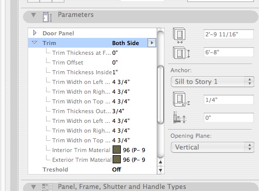
In section, I have finally gotten the door frame to align itself properly with the wall, however the casing on either side is misaligned.
In the following posts are images of the complex profile window, and the door selection settings.
I think I've adjusted every setting that's available - without success - and I don't see the option spoken of in the preceding posts.
Does anyone have any ideas?
In the following posts are images of the complex profile window, and the door selection settings.
I think I've adjusted every setting that's available - without success - and I don't see the option spoken of in the preceding posts.
Does anyone have any ideas?
Anonymous
Not applicable
Options
- Mark as New
- Bookmark
- Subscribe
- Mute
- Subscribe to RSS Feed
- Permalink
- Report Inappropriate Content
2008-07-25 02:36 AM
Anonymous
Not applicable
Options
- Mark as New
- Bookmark
- Subscribe
- Mute
- Subscribe to RSS Feed
- Permalink
- Report Inappropriate Content
2008-07-25 02:37 AM
Anonymous
Not applicable
Options
- Mark as New
- Bookmark
- Subscribe
- Mute
- Subscribe to RSS Feed
- Permalink
- Report Inappropriate Content
2008-07-25 02:38 AM
Learn and get certified!

Related articles
- Finish of complex profile to wrap at the top in Modeling
- IFC Beams not joining in Collaboration with other software
- Complex Profile - Fill Showing Outline in Section but not Profile Manager in Modeling
- Complex Profiled Wall's strange appearance!!! in Documentation
- Plan view of doors in complex profile walls needs to be fixed... in Documentation
Still looking?
